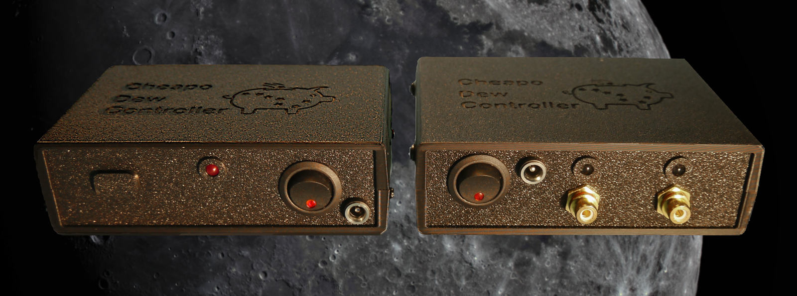
Introducing CheapoDC
The Cheapo Dew Controller, or CheapoDC, is a DIY astrophotography dew controller with the goal of being cheap, simple and easy to both build and use with:
- Low cost off the shelf components including an ESP32-C3 SuperMini, ESP32-C3 SuperMini expansion board, a dual MOSFET module for each output and a 12V to 5V buck converter, plus some protoboard, RCA jacks, 12V barrel jacks and wire.
- No coding or Arduino IDE experience necessary with both WebFlash and Web OTA Update support.
- Comprehensive Web UI for configuration of dew controller operation and management of the device setup.
- Flexibility to support from two to six power outputs, four of which may be used as additional dew controller outputs or independently configured and controlled as PWM or On/Off outputs.
- Dew Controller calculations driven by choice of weather information from one of:
- Open weather api services, Open-Meteo or OpenWeather.
- Personal weather station integration via the CheapoDC API or INDI driver.
- Optional SHT3x humidity sensor supported as of firmware V2.3.0.
- INDI and StellarMate support 'out-of-the-box' and an open API for any third party integrations.
- Build cost of US$30.00 to US$50.00 depending on the number outputs.
The CheapoDC repository page contains the firmware, dew controller algorithm, Web UI and API details. Any issues or questions can also be raised there.
CheapoDC Example Builds
The ease of building the CheapoDC is dependent on the number of controller outputs. Each output requires a MOSFET module and each module requires six connections. Two connections for 12 volt power input, two for the controlled power output and then two connections to the ESP32-C3 to trigger the MOSFETs. This means that a minimal two output controller requires a dozen connections and wires for the outputs. Fairly easy and manageable. A controller with the maximum six outputs requires three dozen connections and wires for the outputs. Not particularly complex, but fitting all those wires in a small case can be a lot less easy and manageable.
I use devices with two RCA outputs since I only have need to control two dew straps on my rigs. The basics of the original CheapoDC 2-Output build is shown on the main CheapoDC repository page. However, many astrophotographers require more than two dew controller outputs and would also like the option to control other accessories.
This document provides details, including parts list, assembly steps and 3D case, for building a 3‑Output CheapoDC and a 6‑Output CheapoDC. Control of three outputs should cover almost all situations where dew heater straps are required while continuing to be very easy to build. Six outputs provides the flexibility to control several dew heater straps as well as some 12V accessories such as a camera cooler.
Note: Support for the optional SHT3x humidity sensor was added after these builds were documented. Basic information about adding the SHT3x sensor is included in this document but detailed information is included in supplemental documentation on adding the sensor.
Parts List
The following table lists the parts used in the builds and the number of each item required for each build version. The Item Names support popovers with images of the item. The Item Costs provide links to examples on AliExpress. The links are for reference purposes and not an endorsement to purchase from the link.
| Item | 3‑Output Number | 6‑Output Number | Item Cost | Comments |
|---|---|---|---|---|
| ESP32-C3 SuperMini | 1 | 1 | US$3.00 | Often comes with the pin headers needing to be soldered. |
| ESP32-C3 SuperMini Expansion Board | 1 | 0 | US$3.00 | Used in 3‑Output build to simplify the build. |
| Dual MOSFET Module | 3 | 6 | US$1.00 | One required per output. |
| LM2596 | 1 | 1 | US$1.50 | DC to DC buck converter to reduce 12V input to 5V for the ESP32-C3. Needs to be set to correct output voltage before use. |
| 12V Barrel Jack | 1 | 3 | US$1.00 | 5.5mm x 2.1mm barrel jack. Used to connect 12V power supply to the CheapoDC and for 2 outputs on the 6‑Output version. |
| RCA Jack | 4 | 4 | US$1.00 | Commonly used for dew heater straps. An extra one is used for the 3‑Output build to make a test LED. |
| Rocker Switch | 1 | 1 | US$0.50 | SPST rocker switch. This one has an LED integrated into the switch which will be used in the 6-Outlet build. |
| RUEF500 PPTC | 1 | 2 | US$0.10 | 5A PPTC resettable fuse. |
| Female Pin Header | 0 | 2 | US$0.50 | 2.54mm, 8-pin female headers used for the ESP32-C3-board in the 6‑Output build. You can also use longer female headers (seen in the male header link below) and cut them down. |
| Male Pin Header | 2 | 2 | US$0.20 | 2.54mm, male pin header used for Dupont jumper connection points. 40-pin headers are easily cut to size. |
| Protoboard | 0 | 1 | US$1.00 | Used in the 6‑Output build for ESP32-C3-board and Power-board. A single 6cm X 8cm piece should be enough for both boards. |
| Red LED | 1 | 0 | US$0.05 | 5mm red LEDs used in the 3‑Output build for the Status LED and a test LED. |
| 12V Red LED | 0 | 6 | US$0.10 | 5mm with pre-wired resistor for 12v. Optional for the 6‑Output build. See comments on these LEDs in the 6-Outlet build notes. |
| 3KΩ resistor | 1 | 1 | US$0.10 | Used for the status LED. Used directly with the status LED in the 3‑Output build and used with the 2N2222 transistor in the 6‑Output build. Getting a kit with an assortment of ¼W resistors may be an option. |
| Dupont jumpers | 1 | 0 | US$2.00 | Package of 20, Female to Female Dupont jumpers, 10cm long . Used with in the 3‑Output build to connect between pin headers. May also optionally be used in the 6‑Output build. |
| 2N2222 | 0 | 1 | US$0.10 | Used on the Power-board for the 6-Outlet build. Allows the ESP32-C3 to control the Switch LED as a Status LED. |
| Optional items | ||||
| ESP32-C3 SuperMini Expansion Board | 0 | 1 | US$3.00 | Instead of creating your own ESP32-C3-board an expansion board may be used instead. Requires an alternate case bottom. |
| Red LED | 1 | 2 | US$0.05 | 5mm red LED used to make a test LED for output verification instead of using a voltmeter.. |
| 510Ω resistor | 1 | 2 | US$0.10 | Used with the Red LED to make a test LED for output verification instead of using a voltmeter. Getting a kit with an assortment of ¼W resistors may be an option. |
| RCA Plug | 1 | 1 | US$1.00 | Used to make the LED test tool for output verification. Also useful if using a voltmeter for verification. |
| 12V 5.5x2.1mm Barrel Plug | 1 | 0 | US$1.00 | Used to make the LED test tool for output verification. The 6‑Output build uses both RCA and Barrel jacks. |
| SHT3x Humidity Sensor | 1 | 1 | US$1.50 | Optional SHT30 humidity sensor. |
| 3.5mm 4-pole Audio Plug | 1 | 1 | US$0.50 | Connector required for optional SHT30 humidity sensor. 4-pole required. |
| 3.5mm 4-pole Audio Jack | 1 | 1 | US$1.25 | Jack required for optional SHT30 humidity sensor. 4-pole required. |
Additional Items
-
Silicone wire. Silicone wire is very flexible and much easier to work with in small spaces, especially with the tight 6-Outlet build. You will need to pick the gauge of wire used based on your application and expected current handling. My dew straps are 15 to 18 watts or 1.25 to 1.5 amps at 12 volts. Current ratings by wire gauge shown below.
Silicone Wire Current Ratings
Wire Gauge Current Rating Used For 16 AWG 10 Amp Main power input. 18 AWG 6 Amp MOSFET power bus. 3 outputs at 1.5 amps max. 22 AWG 3 Amp MOSFET to Output jack connections. 28 AWG 0.8 Amp GPIO signal connections. - 3D-printed cases discussed in the next section.
- An assortment of
self-tapping pan head screws are required to attach the different modules to the 3D
printed case bottom and to hold the case together.
- M2x5mm Screws: 2 for each MOSFET module, 2 for the ESP32-C3 expansion board.
- M3x5mm Screws: 2 for each of the 6‑Output Power-board and ESP32-C3-boards.
- M3x6mm Screws: 4 to hold the case top and bottom together.
- Heat shrink tubing to cover soldered connections and wire splices. There are a lot of wires pressed into a small space with these builds and exposed connections should be minimized to prevent shorts. Electrical tape may also be used but heat shrink tubing is much easer to use and more resilient.
- The 6-Outlet build uses a couple of extra connectors that are used to make the wiring easier. These include Dupont connectors, Molex KK-254 connectors and screw terminal blocks. These require a crimping tool and some patience so you may choose to use direct soldering of the wires or pre-made Dupont jumpers instead.
- If adding support for the optional SHT3x humidity sensor, 4 core cable is needed to build a sensor probe. See the documentation on adding the sensor.
Cost
Costing (based on mid-2025 numbers) is just an estimate but for the 3‑Output build there's less than US$20.00 in core parts and for the 6‑Output build there's about US$25.00 in core parts. Each of them need a case and some screws which should be less than US$25.00 or cheaper if you can print your own case. The next section discusses the two 3D-printed cases designed for these builds.
3D-printed Cases
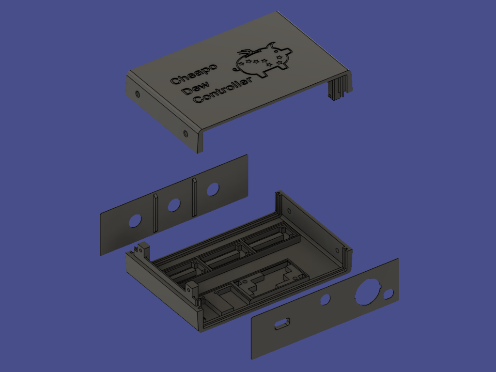
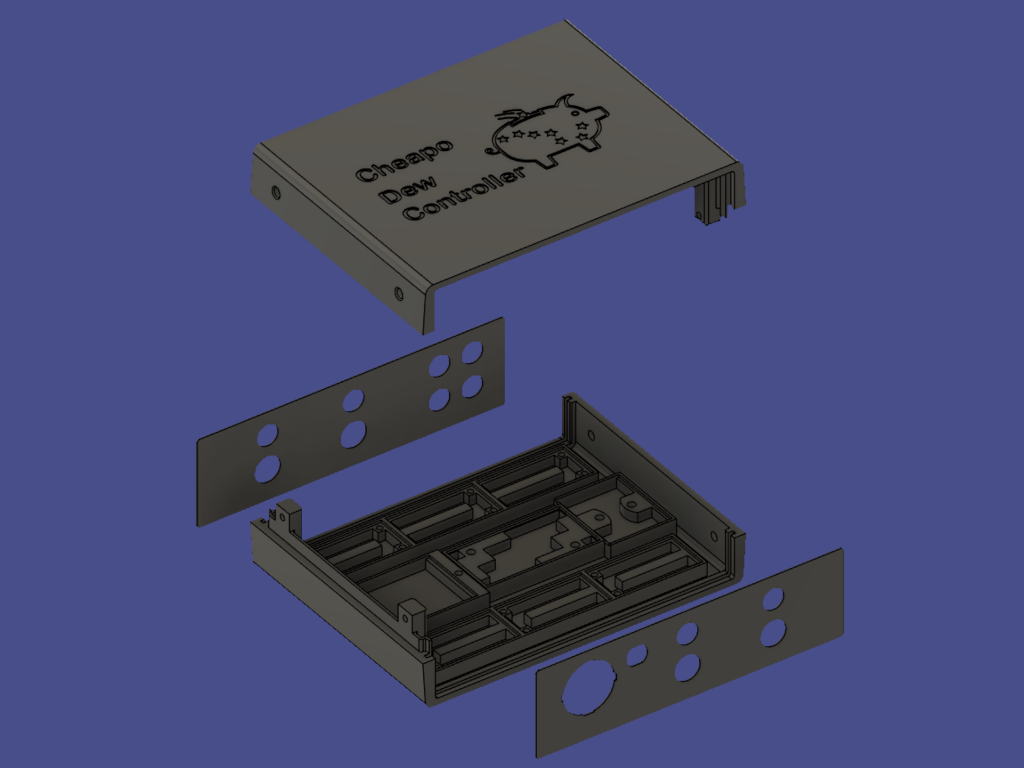
The cases for the 3‑Output and 6‑Output builds are 128mmx85mmx38mm and 128mmx98mmx38mm (WxDXH), respectively. Both consist of a bottom and top piece with slots that hold a front and back panel. The bottom pieces are designed to hold the modules used in each build and allow them to be screwed down. The panels are designed to hold the jacks, switches and LEDs. The front panel is referred to as the switch-panel and the back panel as the output-panel in the build description. The top and bottom pieces are held together with 4 M3x6mm screws.
There are alternate versions of each of the switch-panels with added 8.5mm openings for the 3.5mm audio jack used to connect the SHT3x humidity sensor. One for the 3‑Output build and one for the 6‑Output build. If you wish to support the use of an SHT3x humidity sensor then these alternate switch panels are required. See the documentation on adding the sensor for more information.
Besides the top, bottom and panels there are some additional pieces:
- The 3‑Output switch-panel has an opening to expose the USB port on the ESP32-C3. A 3D printable press fit plug is available.
- The LEDs that are mounted in the panels are held in place by a 3D printable holder with a press fit backing piece. There's also a printable tool to drive the backing piece onto the LED holder.
- There are two sets of panels for the 6-Outlet case. One set with LED holes for each output and one set without LED holes.
- There are two versions of the 6‑Output case bottom. One which provides a mounting spot for the protoboard based ESP32-C3-board and one which provides an alternate mounting for the ESP32-C3 SuperMini Expansion board.
- The protoboard based Power-board requires a mounting ring to hold it to the case bottom. It is also 3D printable.
Both STL and STEP files for the cases can be found in the CheapoDC GitHub repository along with additional information about the cases.
3‑Output Build
The 3‑Output CheapoDC is significantly simpler to build than the 6‑Output version due to the reduced number of outputs that need to be connected. This build has all three outputs set up for dew straps with RCA jacks. The third output could be changed over to a switched 12 volt barrel jack or left out completely if needed.
Wiring requires a combination of 10cm female to female Dupont jumpers and 18 gauge silicone wire. If you plan to use the CheapoDC for more than a total of 72 Watts or 6 amps at 12 volts then you may want to use 16 gauge wire for the power harnesses. You may also want to use a PPTC resettable fuse with a higher rating or one per output.
3-Output Assembly Steps
Note: The assembly steps below DO NOT include details about adding support for the SHT3x humidity sensor. Read the documentation on adding the sensor for more information.
-
Solder pins to modules.
Solder 2.54mm header pins to the MOSFET and buck converter modules. The buck converter requires a single pin at each corner which can be a bit difficult to solder. I used a piece of painter's tape pierced by a single pin and taped to the buck converter to hold the pin in place while I soldered it. The tape is removed after soldering. The MOSFET modules each get a 4 pin header which provides for 2 trigger and 2 ground pins. This allows the ground connection to be daisy chained between the modules. One of the trigger pins on each MOSFET module must be connected to one GPIO pin on the ESP32-C3 expansion board.
If your ESP32-C3 came without the header pins soldered to the board, solder those header pins onto the module board at this time.
-
Mount modules to the case bottom.
Mount the MOSFET modules, buck converter module and ESP32-C3 expansion module in the case bottom. This is shown in the image to the right. The ESP32-C3 expansion board should be screwed down to the case bottom before the ESP32-C3 is installed. Mounting the modules now will help with the next step.
3‑Output Build - Modules Installed -
Create power harnesses.
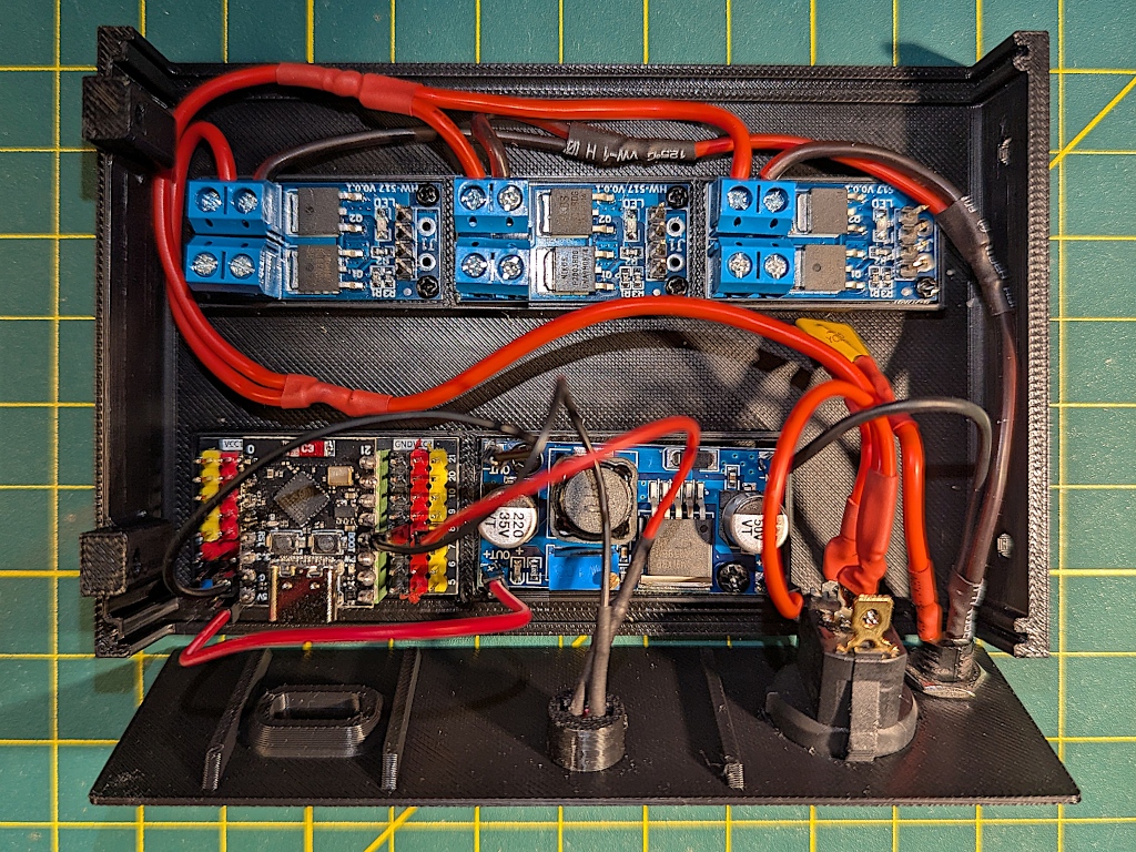
3‑Output Build - Power Harness Routing There are two power harnesses, one for 12V and one for ground. Use the populated case bottom to measure the lengths of wire needed for the harnesses.
The 12V harness is connected to one pole of the SPST rocker switch and feeds to the left around the end of the MOSFET modules. See the image to the right. Cut a single wire long enough to reach the farthest right MOSFET module plus at least 5cm. Then splice in two shorter pieces of wire for the first two MOSFET modules. Keep the wires long, we'll cut them down later. Cover the splices with tape or heat shrink tubing.
Make the ground harness in a similar manner except that it routes from the negative lead of the 5.5mm x 2.1mm barrel jack around the other end of the MOSFET modules.
Do not attach the wiring harnesses, they will be attached in a future step.
-
Install the Status LED.
First solder and then install the Status LED. Trim the longer positive (anode) lead of the red LED and then solder the 3K resistor to the positive lead. Trim the negative (cathode) lead. Cut the ends off a couple of Dupont jumpers and strip the ends. Cut and solder the Dupont jumpers to the resistor and negative lead. The 3D files for the case include an LED holder which is used to mount the LED to the case switch-panel. The LED holder is a tight press fit and a 3D printable tool is also provided for pressing it in place. This should be done before the switch and barrel jack are installed.
The positive LED lead connects to GPIO pin 8 on the ESP32-C3 while the ground lead should be connected to a ground pin on the ESP32-C3 expansion board.
-
Install and Solder the switch and 12V barrel jack.
Note that the switch and barrel jack may need to be installed in the switch-panel first since they may not be be able to be installed after the these connections are made. Solder the connections between the rocker switch and the barrel jack.
The positive lead of the barrel jack is connected to the switch through the PPTC fuse. First solder a couple of leads onto the PPTC then solder one lead to the positive lead of the barrel jack and the other lead to one of the pole leads of the rocker switch.
-
Connect the power harnesses and buck converter to the switch and barrel jack.
Cut the end off a Dupont jumper and strip the wire. Solder the Dupont jumper and the ground harness to the negative lead of the barrel jack. The Dupont jumper connects to the IN- pin on the buck converter.
Similar to the ground connections, cut the end off another Dupont jumper and strip the wire. Solder the Dupont jumper and the 12V harness to the other free pole of the SPST switch. The Dupont jumper connects to the IN+ pin on the buck converter.
DO NOT CONNECT THE OUTPUTS OF THE BUCK CONVERTER TO THE ESP32-C3 UNTIL THE OUTPUT IS ADJUSTED IN THE NEXT STEP.
-
Adjust buck converter to 5 volts.
This is done by connecting a voltmeter to the output of the buck converter and adjusting the potentiometer on the buck converter until the meter reads 5 volts. Since the wiring for power was completed in the previous step you should be able to plug in a 12 volt supply to the barrel jack and switch on the buck converter. With a small screw driver adjust the potentiometer on the buck converter by turning the small screw until your voltmeter reads 5 volts. Assuming you have not previously adjusted the buck converter, it should be set to maximum and show about 12 volts. Turning the screw counter clockwise will reduce the output voltage. It may take quite a few turns before you see any change in the output and then it will change quickly.
You can now connect the buck converter to the ESP32-C3 expansion board with a couple of Dupont jumpers. The Out+ buck converter pin connects to the 5V ESP32-C3 pin while the Out- buck converter pin connects to the G ESP32-C3 pin.
-
Install the power output jacks.
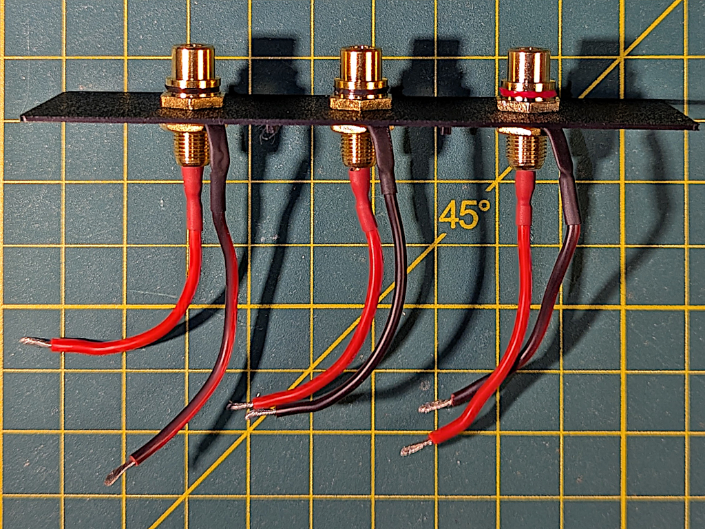
3‑Output Build - Output Panel If using RCA jacks similar to ones shown then all the soldered connections to the jacks can be completed before they are mounted in the case output-panel. Cut six pieces of wire long enough to reach from the output-panel, over the MOSFET modules and then around to the MOSFET output screw block connecters. Leave enough length to bend and insert the ends of the wires into the screw terminals. Solder the wires to the positive and negative leads on the RCA jacks. The center of the jack is positive (12V) while the outer barrel is negative (ground).
Note that polarity doesn't usually matter for Dew Straps since they are simple resistive loads. But, keeping the polarity correct for these outputs is good practice. In particular if you plan to use the third output for a different purpose then you should definitely keep the polarity correct.
-
Install CheapoDC firmware.
If you have not installed the CheapoDC firmware onto the ESP32-C3 then do it now. The easiest way to do this is to connect the ESP32-C3 to your computer using a USB cable and then use the WebFlash tool to upload the latest firmware. After the firmware is uploaded, follow the steps outlined in First Time Device Configuration to setup your CheapoDC:
- Configure the WiFi settings for your network.
- Set Output GPIO pins as follows:
- Output 0 = GPIO 0
- Output 1 = GPIO 1
- Output 2 = GPIO 3
- Output 3 = -1 (Disabled)
- Output 4 = -1 (Disabled)
- Output 5 = -1 (Disabled)
- Set the Mode for Outputs 0, 1 and 2 to Controller.
- Leave the Status LED GPIO pin at the default of 8.
- Also, go to the Controller Configuration page and set the Controller Mode to Off.
-
Finish the wiring.
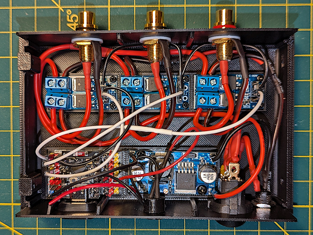
3‑Output Build - Wiring Complete Connect everything together as shown in the image. Make sure to install the ESP32-C3 module into the expansion board before connecting all the wiring. It will be harder to insert the module once all the wiring is in place.
First connect the power harnesses to the MOSFET modules. Insert the case switch-panel into the base and route the ground harness to right and around the end of the MOSFET modules. Cut the ground wires to length so that they will reach the appropriate VIN- connection on each module. Strip the ends, insert into the terminals and tighten the screws. Repeat for the 12V power harness, routing it to the left and around the end of the MOSFET modules. Cut the wires to length so that they will reach the appropriate VIN+ connection on each module. Strip the ends, insert the ends into the terminals and tighten the screws.
Use two Dupont jumpers to daisy chain the ground pin connections between the MOSFET modules. These will be routed under the RCA jacks on the output-panel.
Insert the output-panel into the slot on the case bottom and route the wires from the RCA jacks to the MOSFET modules. Cut the wires to length so that they will reach the appropriate OUT+ and OUT- connections on each module. Strip the ends, insert the ends into the terminals and tighten the screws.
Connect the ESP32-C3 to the MOSFET modules. Use one Dupont jumper to connect the ground pin on the left-most MOSFET module to any of the ground pins on the ESP32-C3 expansion board (black pins). Use two more Dupont jumpers to connect the trigger pins on the left-most MOSFET module and center MOSFET MODULE to GPIO pins 0 and 1 on the ESP32-C3 expansion board (yellow pins). If using 10cm long Dupont jumpers then you will need to cut the ends off two of them and splice them together to make a longer wire. This will then be used to connect the trigger pin on the right-most MOSFET module to GPIO pin 3 on the ESP32-C3 expansion board (yellow pin).
The wiring is now complete but before you put the top of the case on we need to test that the outputs work properly.
Do Hardware Verification
Before putting the top on the case verify that everything works. This can be done fairly easily by following the steps in the Hardware Verification section.
6-Output Build
This 6 output device was built for firmware testing and demonstration purposes, not to be used on an actual astrophotography rig and as such this affected some aspects of the design. If you are building a 6‑Output CheapoDC for personal use on your astrophotography rig, consider the following:
- There is an external LED for each output to help with testing. In general, having a lot of flashing red LEDs on an astrophotography rig is not a good idea. Only the status LED should be needed on a 'production' CheapoDC.
- The CheapoDC firmware will support from one to 6‑Outputs. The first two are assumed to be dew controller outputs but the additional four may be configured as dew controller, PWM or boolean (on/off) outputs. This design supports the maximum 6‑Outputs supported by CheapoDC firmware. Four outputs have RCA jacks, commonly used for dew straps, and two outputs have 5.5mm X 2.1mm barrel jacks. The number of outputs and balance of RCA versus barrel jacks can be configured based on personal need.
- I used crimp connectors for connections between the modules to allow for more flexible testing. Crimping Molex or Dupont jumpers is not hard but it requires patience and a crimping tool. If you don't wish to invest in a crimping tool and connectors, soldering the wires is an alternative. The 3‑Output build shows how to use soldering with off-the-shelf Dupont jumper wires.
Protoboards
The primary difference between the 6‑Output build and the 3‑Output build, besides the number of outputs, is that the 6‑Output build requires the two protoboard based boards. Building the ESP32-C3-board and the Power-board should be completed before assembling your 6‑Output CheapoDC.
ESP32-C3-board
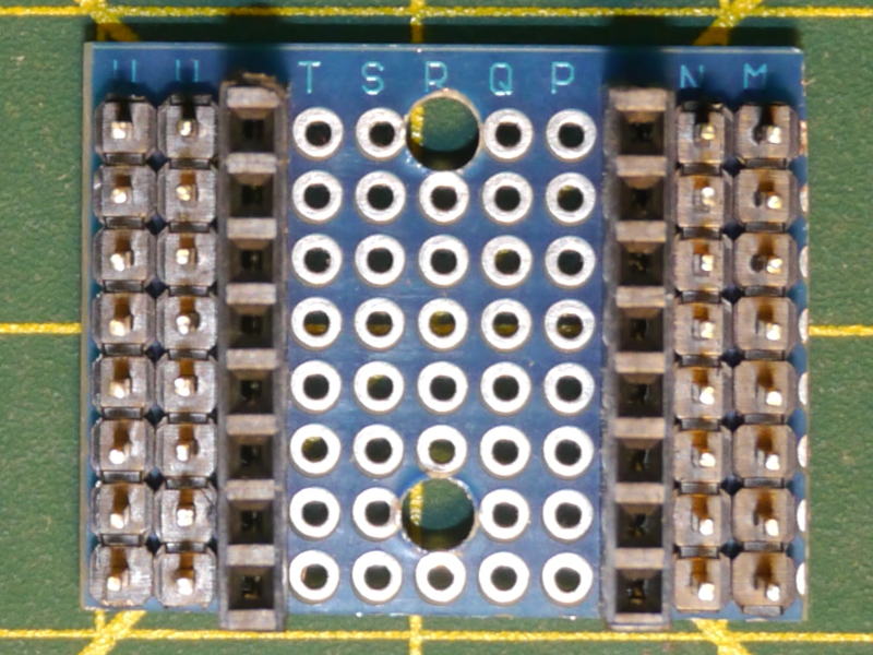
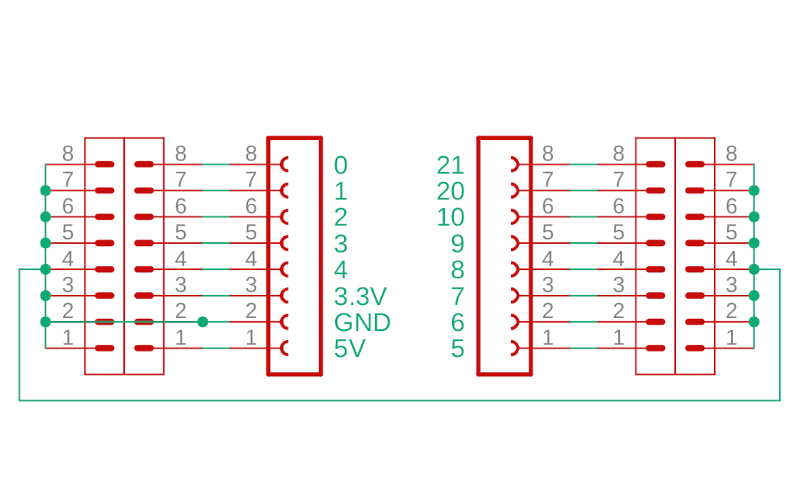
The ESP32-C3-board provides a socket for the ESP32-C3 SuperMini as well as pin headers for power and GPIOs. An image of the board is shown to the right. The schematic below the image shows the connections between the female headers for the ESP32-C3 SuperMini and the male headers for power and GPIO pins. Theres also a row of ground pins on either side.
The board is made by cutting down some protoboard to fit the 30mmx25mm mounting area in the case bottom. The piece should come from the edge of the protoboard where there is a 3mm edging as shown at the top of the image. The orientation of the board is important so that it lines up properly with the screw holes in the base. The board should be 11 holes wide by 8 deep. You'll need to use a small drill bit (3mm) to drill out the mounting holes as shown in the image. Drill the holes before soldering the pin headers. The board image and schematic are both oriented with the ESP32-C3 SuperMini USB socket at the bottom.
The board pin to pin connections are all soldered on the underside of the board. When connecting the two rows of ground pins together the connecting wire needs to cross through the middle of the bottom of the board or across the top otherwise the board will not mount properly into the case bottom.
Soldering all the pins together on the bottom of the board can take a lot of patience and you must be careful not to short pins together that should not be connected. Once done its good to test all the pins with a multimeter to make sure that they are all connected properly. If you don't want to spend the time putting this board together then an alternative is to use an ESP32-C3 SuperMini Expansion Board as was used in the 3‑Output build. A version of 6‑Output build case bottom that supports mounting the ESP32-C3 SuperMini expansion board is available in the GitHub repository. The expansion board is a little larger than the protoboard based board and will make routing the power harnesses a little tighter.
Power-board
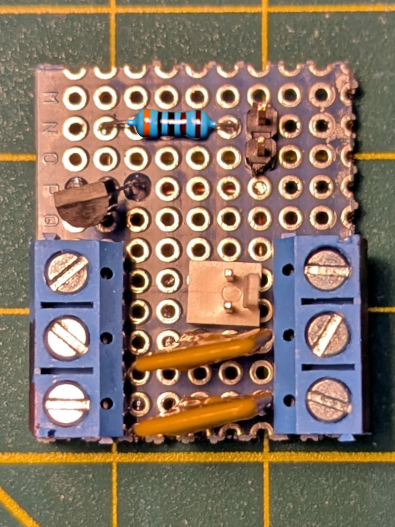
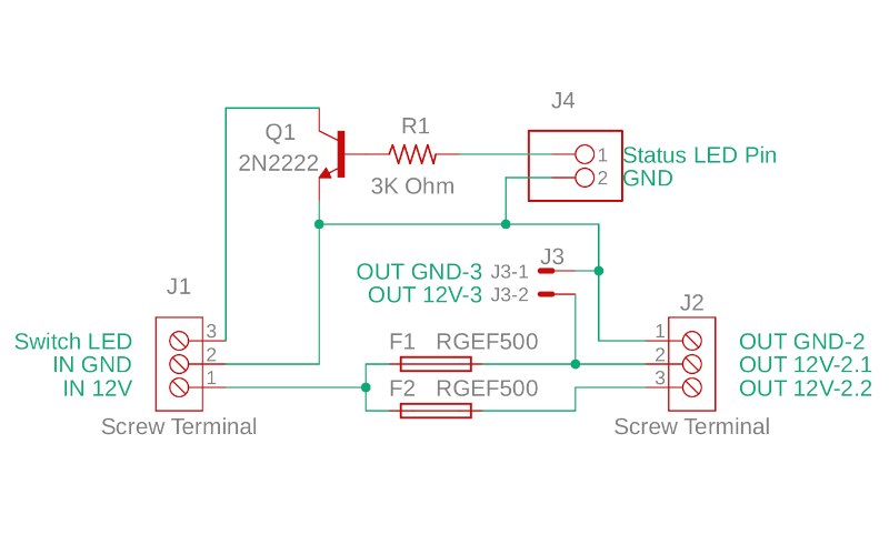
The Power-board provides a place to connect the input power to the two resettable fuses and then to the two MOSFET power lines. It also has the 2N2222 transistor used to switch the LED light in the power switch. The image includes both a completed Power-board as well as the schematic. The screw terminal blocks, J1 and J2, have 5.08mm spaced pins. J3 is a 2 pin male 2.54mm header while J4 is a 2 pin Molex KK-254 male jack. The terminal blocks could be replaced with direct soldering to the Power-board. Male 2.54mm pin headers could be used for both J3 and J4 instead of using a Molex KK-254 jack.
This piece of protoboard is 27 mm wide by 32 mm deep. The size is important for it to fit in the spot reserved for it in the case bottom. Unlike the ESP32-C3-board, the Power-board is held down to the case bottom using a screwed in 3D-printed hold down ring. Similar to the ESP32-C3-board, solder the connections on the underside of the board.
6-Output Build Assembly
Once the ESP32-C3 and Power-boards are completed, its time to move on to the assembly steps. These build steps are very similar to the 3‑Output build steps.
Note: The assembly steps below DO NOT include details about adding support for the SHT3x humidity sensor. Read the documentation on adding the sensor for more information.
-
Solder pins to modules.
Solder 2.54mm header pins to the buck converter module. The buck converter requires a single pin at each corner which can be a bit difficult to solder. I used a piece of painters tape with pierced with a single pin and taped to the buck converter to hold the pin in place while I soldered it. The tape is removed after soldering.
For the 6‑Output build I used 2-pin Molex KK-254 headers instead of the 2.54mm male pin headers used in th the 3‑Output build. The Molex KK-254 headers have a friction lock that helps to hold the female connector in place while the many wires in the 6‑Output build are compressed into the case. If you want to avoid crimping your own wires then use the pin headers used in the 3‑Output build with Dupont jumpers.
If your ESP32-C3 came without the header pins soldered to the board, also solder those header pins at this time.
-
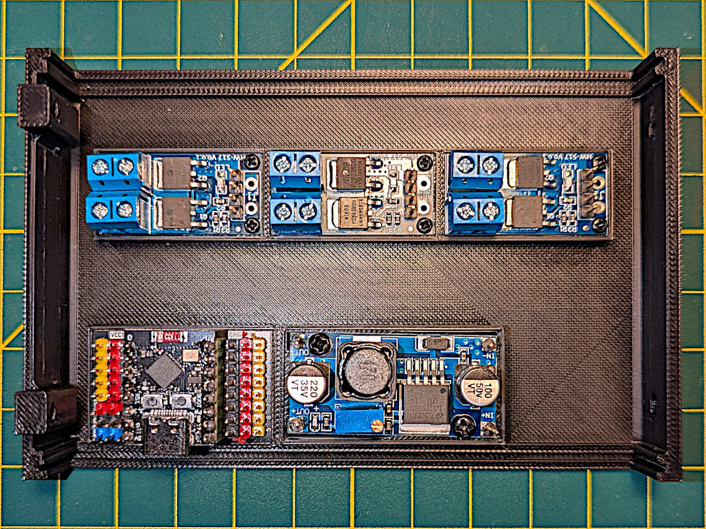
Mount modules to case bottom.
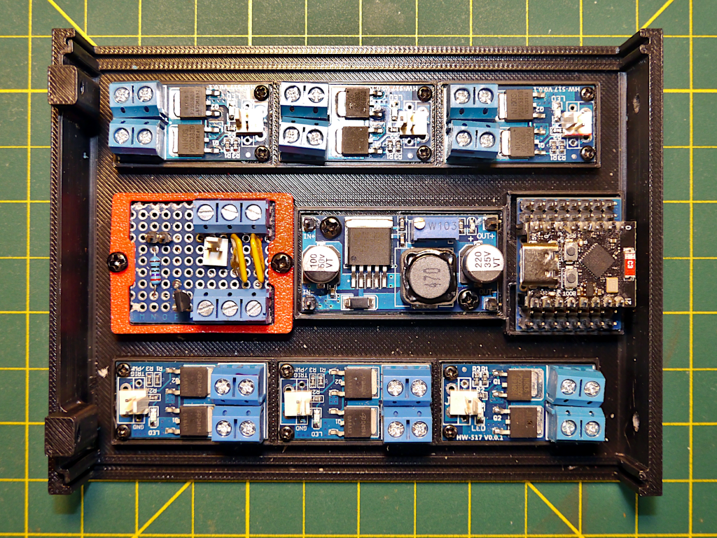
6‑Output Build - Modules Installed Mount the MOSFET modules, buck converter module, ESP32-C3-board and Power-board in the case bottom as shown in the image. The ESP32-C3-board should only fit in one orientation. The ESP32-C3 SuperMini USB port should face to the inside of the case to keep it accessible. Use the 3D-printed mounting ring (red in the image) to hold down the Power-board so that the power input (bottom in the image) and output (top in the image) connection blocks are on the correct side. Mount the buck converter so that the input pins are next to the Power-board.
-
Create power harnesses.
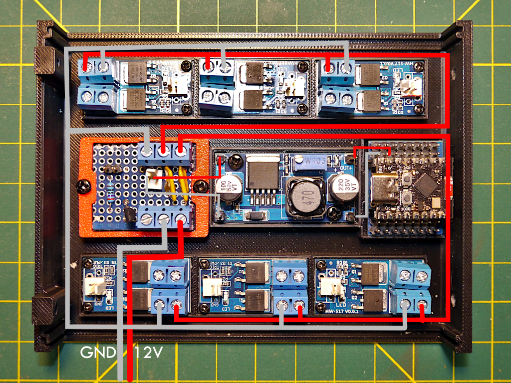
6‑Output Build - Power Harness Routing There are three power harnesses, one 12V harness for each of the two sets of MOSFET modules and one ground harness. Use the populated case bottom to measure the lengths of wire needed for the harnesses using the routing indicated in the image. Red lines are 12V and dark grey lines are ground. The 12V harnesses use 18 gauge wire while the ground harness uses a combination of 16 and 18 gauge wire.
The 12V harnesses are each connected to one of the 12V output terminals on the Power-board. Using the image cut a single wire for each long enough to reach from the 12V output terminal to the farthest MOSFET module on the route plus at least 5cm. Then splice in two shorter pieces of wire for the first two MOSFET modules on each harness. Keep the wires long, we'll cut them down later. Cover the splices with tape or heat shrink tubing.
Make the ground harness in a similar manner except that it routes from the negative terminal of the Power-board. There is a shorter piece of 16 gauge wire that goes from the Power-board ground terminal to the first splice that splits the ground into two 18 gauge wires running to three MOSFET modules each.
-
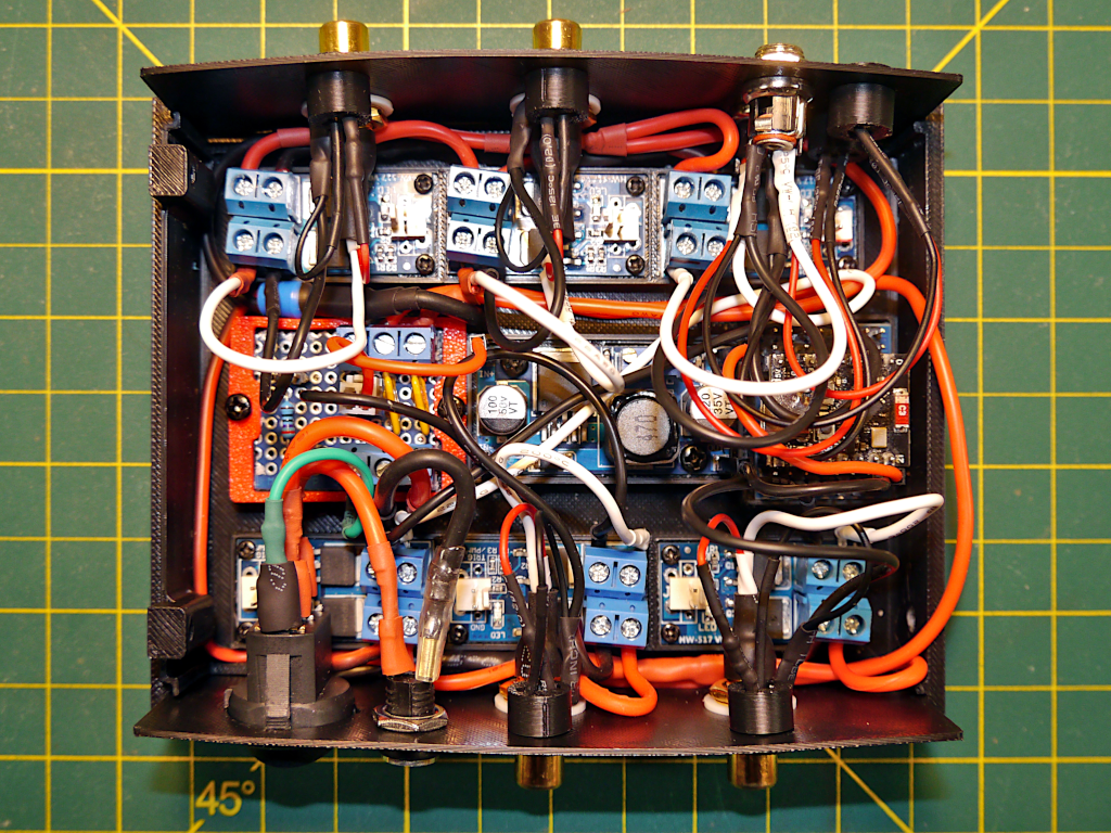
Connect the power harnesses.
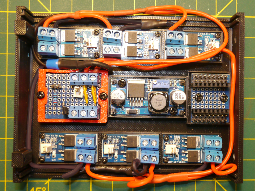
6‑Output Build - Installed Power Harness Connect the power harnesses to the Power-board. The image shows the installed power harnesses. Install the ground harness first routing it to the left and around the end of the MOSFET modules. Cut the spliced wires to length so that they will reach the appropriate VIN- connection on each module. Strip the ends, insert and tighten the screws.
Repeat for the two 12V power harnesses, which are routed to the right and around the end of the MOSFET modules. Cut the spliced wires to length so that they will reach the appropriate VIN+ connection on each module. Strip the ends, insert and tighten the screws.
Keep the power harnesses tight to the MOSFET modules on the case panel sides. The space between the panels and the MOSFET modules is tight and the wires will be compressed when the case top is installed. The RCA jacks and barrel jacks also stick out over the MOSFET modules leaving very little room.
-
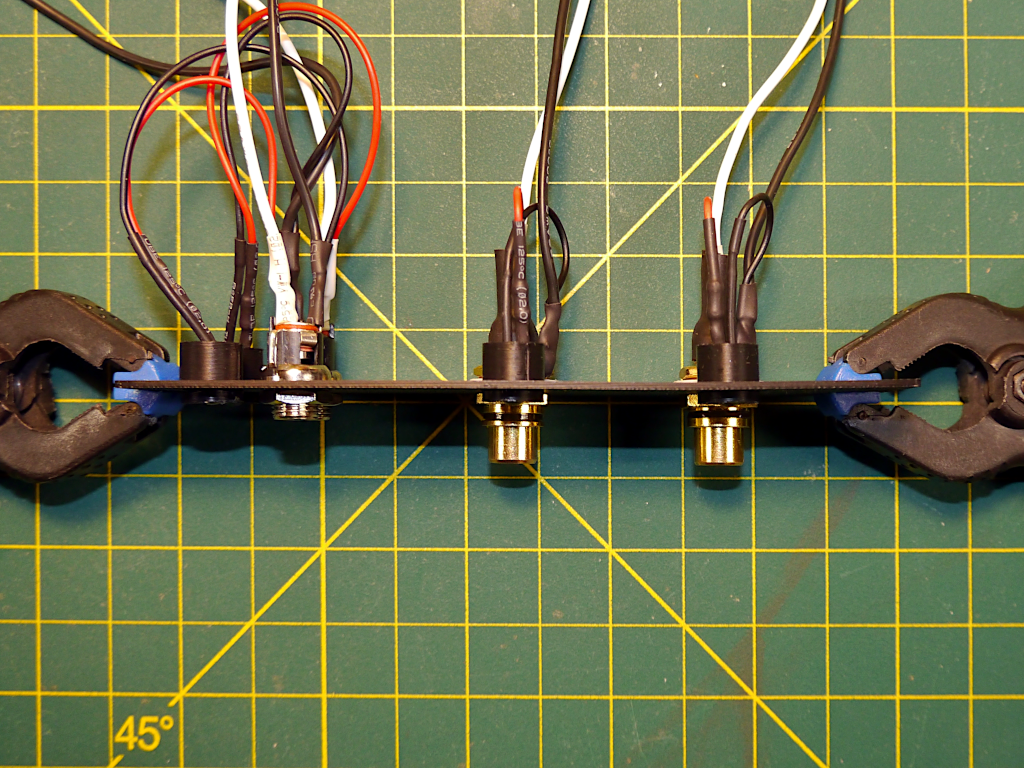
Assemble the Switch-panel
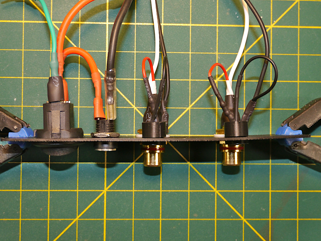
6‑Output Build - Switch Panel The 6‑Output switch-panel the power switch and power input jack as well as two RCA jacks for for CheapoDC outputs 0 and 1. If building with the output LEDs then there is also one LED for each of the two outputs. The image shows the switch-panel assembled with connections attached.
Note that shrink tubing has been used to cover and insulate the solder joints. If using the output LEDs then the RCA jack threaded barrel should also be insulated with either shrink tubing or electrical tape. The RCA jacks are very close to the tops of the MOSFETs in the MOSFET modules and the threaded barrels can short out the MOSFETs if they touch. The shrink tubing or tape will help to prevent this. This is not an issue when NOT using output LEDs because the RCA jacks are mounted higher on the switch-panel.
Remember to slide heat shrink tubing onto wires before soldering since many of the solder joints create closed loops that will not allow the shrink tubing to be placed on the wires after soldering. Keep the tubing back from the joint while soldering and then slide it over the joint and heat it to shrink it.
- If using output LEDs install the two 12V LEDs into the smaller holes above the RCA jack holes using the 3D-printed holder and backer. Trim the LED wires down to about 5cm and strip the ends.
- Cut 4 pieces of 22 gauge wire long enough to reach from the switch-panel RCA jack holes over the MOSFET modules and then around to the MOSFET output screw block connecters. If using RCA jacks similar to those shown in the parts list then solder one of the pieces of wire and a black LED wire to the tabs of each of the two RCA jack ground washers. Now mount the RCA jacks into the switch-panel, in the holes under the LEDs, and tighten their holding nuts. A red LED wire and piece of 22 gauge wire should now be soldered to the positive terminal of the RCA jacks.
- Install the rocker switch and barrel jack into the switch-panel. Solder a piece of 16 gauge wire to the negative lead of the barrel jack leaving the wire long enough to reach the IN GND terminal of J1 on the Power-board. Solder a piece of 16 gauge wire to the positive lead of the barrel jack and leave it long enough to reach the switch. Solder the other end to one of the pole tabs for the single pole of the switch. Solder a piece of 16 gauge wire to the other tab of of the single pole and leave it long enough to reach the IN 12V terminal of J1 on the Power-board.
- Solder a piece of 22 gauge wire to the switch LED ground tab and leave it long enough to reach the Switch LED terminal of J1 on the Power-board.
-
Install the Switch-panel.
6‑Output Build - Switch Panel installed The switch-panel is installed in the slot in the case bottom, as shown bottom of the power harness image. When cutting wires to reach the Power-board and MOSFET modules make sure they are long enough to allow the switch-panel to be removed and/or inserted into the case bottom panel slot.
Connect the 12V and ground wires from the rocker switch and barrel jack to the Power-board. Cut the wires to length and strip the ends. Then insert the 12V wire into IN 12V terminal of J1 and tighten down the terminal screw. Do the same with the ground wire connecting it to IN GND terminal of J1. The switch LED ground wire can also be connected to the Switch LED terminal of J1.
Connect the two RCA jacks to the MOSFET modules with the right RCA jack connecting to the right most MOSFET module and the left RCA jack connecting to the middle MOSFET module. Connect the positive leads from the RCA jacks to VOUT+ on the MOSFET modules while the negative leads connect to VOUT-.
DO NOT CONNECT THE OUTPUTS OF THE BUCK CONVERTER TO THE ESP32-C3 UNTIL THE OUTPUT IS ADJUSTED IN THE NEXT STEP.
-
Adjust buck converter to 5 volts.
This is done by connecting a voltmeter to the output of the buck converter and adjusting the potentiometer on the buck converter until the meter reads 5 volts. The Power-board was connected to the switch-panel in the previous step, now connect jumper wires from J3 on the Power-board to the buck converter. Connect OUT 12V-3 from the Power-board to IN+ on the buck converter and OUT GND-3 to IN- on the buck converter.
Connect a voltmeter to the OUT+ and OUT- pins on the buck converter then plug in a 12 volt supply to the barrel jack on the switch-panel and turn on the switch. The buck converter should be powered with a power LED on. With a small screw driver adjust the potentiometer on the buck converter by turning the small screw until your voltmeter reads 5 volts. Assuming you have not previously adjusted the buck converter, it should be set to maximum and show about 12 volts. Turning the screw counter clockwise will reduce the output voltage. It may take quite a few turns before you see any change in the output and then it will change quickly.
You can now connect the buck converter to the ESP32-C3-board with a couple of jumpers with female Dupont connectors on each end. The Out+ buck converter pin connects to the 5V ESP32-C3 pin while the Out- buck converter pin connects to the G ESP32-C3 pin.
-
Install CheapoDC firmware.
If you have not installed the CheapoDC firmware onto the ESP32-C3 then do it now. The easiest way to do this is to connect the ESP32-C3 to your computer using a USB cable and then use the WebFlash tool to upload the latest firmware. After the firmware is uploaded, follow the steps outlined in First Time Device Configuration to setup your CheapoDC:
- Configure the WiFi settings for your network.
- Set Output GPIO Pins as follows:
- Output 0 = GPIO 0
- Output 1 = GPIO 1
- Output 2 = GPIO 3
- Output 3 = GPIO 4
- Output 4 = GPIO 5
- Output 5 = GPIO 7
- Set all of the Outputs to Controller mode.
- Leave the Status LED GPIO pin at the default of 8.
- Also, go to the Controller Configuration page and set the Controller Mode to Off.
-
Build Output-panel.
6‑Output Build - Output Panel The output-panel has the four additional outputs supported by CheapoDC firmware, which may be configured to be either dew controller, independent PWM or Boolean (On/Off) outputs via the Web UI. Two of the outputs have the RCA jacks commonly used by dew straps while two have 5.5mmx2.1mm 12v barrel jacks. The RCA jacks go in the larger holes with LEDs holders in the holes above them. The other four holes are for the barrel jacks and their LEDs. LED holders are stacked to the outside (left) of the panel while the barrel jacks go in the two holes stacked to the inside (right). Picking the right holes is important because they are placed to allow the jacks to fit with the MOSFETs and tight space in the case.
If using output LEDs then all four should be mounted in the case first using the 3D printed LED mounts. The jacks will also need to be inserted in the panel holes before soldering. The soldering instructions for the RCA jacks are the same as in the switch-panel build step.
The barrel jack soldering is very similar to the steps for the RCA jacks. The only difference is that the wires for the bottom barrel jack must be long enough to reach diagonally across the case to the furthest MOSFET module.
Note that polarity doesn't usually matter for Dew Straps since they are simple resistive loads. But, keeping the polarity correct for the RCA jack outputs as well as the barrel jack outputs is good practice. In particular, any output that may be used for a purpose other than dew straps should definitely keep the polarity correct.
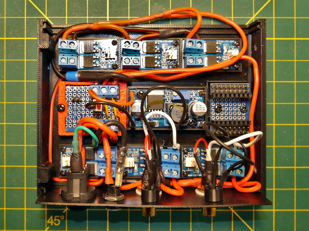
-
Install Output-panel.
6‑Output Build - Output Panel Installed This is where the build becomes significantly less easy. Installing the output-panel requires that the wire leads for the jacks in the output-panel be trimmed to length, the ends stripped and then inserted into the appropriate MOSFET module terminals. There is very little room and inserting the tips of the stripped wires into the terminal blocks can be very frustrating.
It is easiest to start with the bottom 12V barrel jack, upper right of the image, which connects to the MOSFET module diagonally opposite it in the lower left of the image. The space between the Power-board input J1 terminal block and the MOSFET module terminal block is very tight. You may need to disconnect the J1 Power-board connections before doing the MOSFET module connections. Then reconnect the Power-board connections.
Work your way, using the image, right to left with the upper barrel jack connecting to the right MOSFET module, the right RCA jack connecting to the middle MOSFET module and then the left RCA jack connecting to the left-most MOSFET module.
-
Finish the wiring.
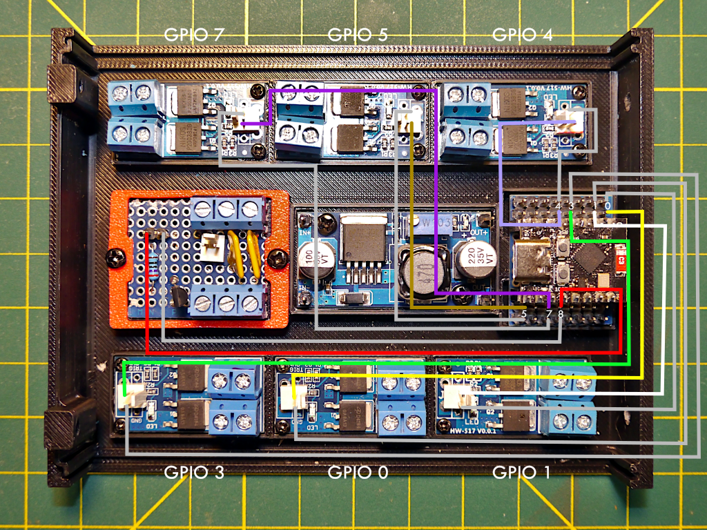
6‑Output Build - GPIO Connections 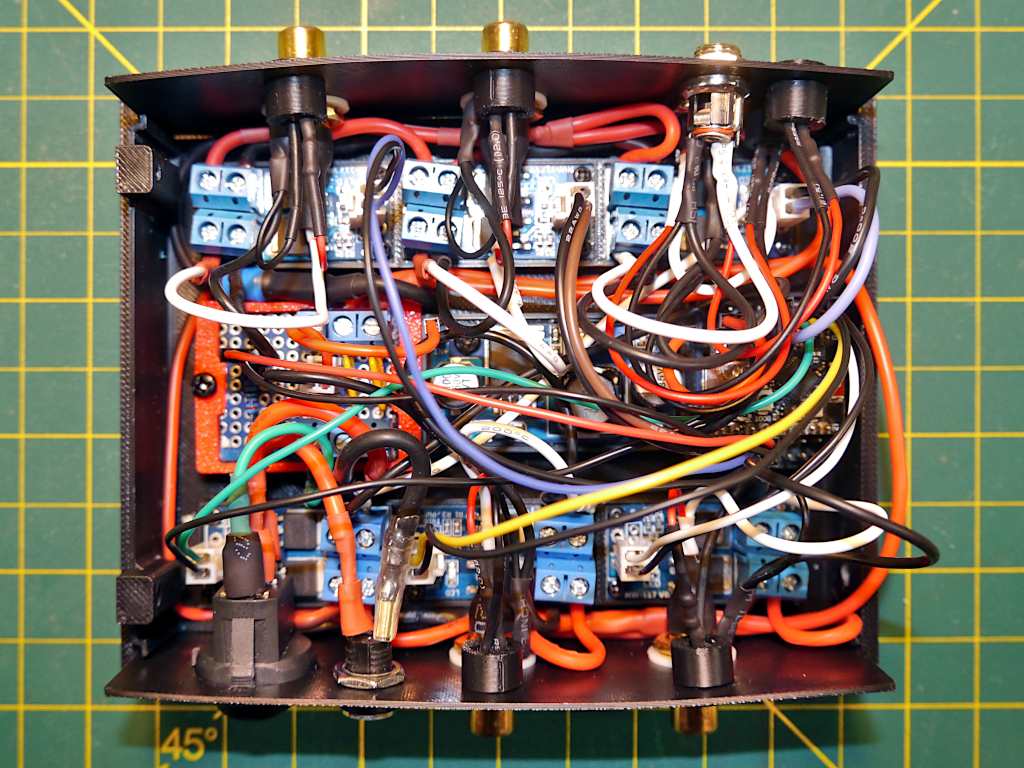
6‑Output Build - Wiring Complete
All that is left is to connect up the GPIO pins to the MOSFET module triggers and then the status LED. Follow the connections as indicated in the GPIO Connections image. It shows which MOSFET modules will be controlled by specific GPIO pins. Hover your cursor here to see a zoomed in view of the ESP32-C3 pin connections.
If you are crimping your own jumpers then cut them to length. If using Dupont jumpers then 10cm should work for the four MOSFET modules closest to ESP32-C3. For the two farthest modules you'll need longer jumpers or will need to splice a couple of 10cm jumpers together to reach. Similarly a longer jumper is required for the status LED connection from GPIO 8 to the Power-board.
The wiring is now complete but before you put the top of the case on we need to test that the outputs work properly.
Do Hardware Verification
Before putting the top on the case verify that everything works. This can be done fairly easily by following the steps in the next section, Hardware Verification.
Hardware Verification
Before putting the top on the case verify that everything works. This can be done fairly easily and the process is roughly the same for both the 6‑Output and 3‑Output builds. Having the output LEDs helps with visual verification of the output of the MOSFET modules but you will still need to check each output jack to confirm the connections to the jacks. There are a couple of ways to verify the outputs are working:
- Use a voltmeter or multimeter to measure the voltage output. Outputs set to an Output Mode of Boolean are easy to measure with a multimeter since they are either On (12 volts) or Off (0 volts). When configured to Controller or PWM Output Mode the measurement may depend on the multimeter. Both of these modes use Pulse Width Modulation (PWM) to switch the outputs between 0 volts and 12 volts 1000 times per second. The amount of power output is determined by how much the output is at 12 volts versus 0 volts, the duty cycle. This may prevent a multimeter from providing useful readings. Making sure you have a load across the output and measuring across the load will provide better readings. For this reason using the next method is often easier and more reliable.
- Making and using a simple LED test lead. This uses an LED set up for 12 volts soldered to an RCA plug and/or 12V barrel plug. Moving the LED from output to output is easy and both On/Off and different PWM settings are easy to visibly observe.
Make an LED Test Lead
To make a simple LED test lead, solder a 12 volt LED to an RCA plug. An LED can be configured for 12 volts by using a current limiting resistor. If you do not have a pre-made 12 volt LED you can make one following the steps to solder up the 3‑Output status LED except with a 3KΩ resistor instead of a 510Ω resistor. The LED positive lead should be connected to the center pin of the RCA plug and the ground lead should be connected to the outer sleeve of the RCA plug.
If you have a 6‑Output CheapoDC with 12V barrel jacks then build a second LED test lead with a barrel plug.
Connection Verification Steps
As mentioned this should be done with the case top removed so that you can see the LEDs that are built into the buck converter and MOSFET modules. Note that the case panels are quite thin and flexible when not supported by the top and bottom case halves. Be gentle while inserting and removing RCA plugs and 12V barrel plugs.
-
Confirm basic ESP32-C3 power connection.
Connect a 12 volt supply to the barrel jack on the switch-panel then switch your CheapoDC on. The Status LED should turn on then off quickly, then after a few seconds start a slow blink as the WiFi connection is established. The status LED should turn off once the WiFi connection is established. If it goes into a fast blink and then stays on there's a WiFi issue and the CheapoDC is in AP mode. You'll need to check the WiFi settings using the steps in First Time Device Configuration.
Trouble shooting:
If the status LED does not blink at all then there may be a connection issue:
- Confirm that the ESP32-C3 is getting power. The red power LED on the ESP32-C3 SuperMini should be on when power is on. There is also an LED on the buck converter that should be On. If either of these LEDs are not lit then there is a power connection issue.
- If using an ESP32-C3 SuperMini expansion board, the board also has a green LED that flashes when the board is powered. If it is not flashing then the expansion board is not getting power. Check the 5V and ground connections.
- The ESP32-C3 SuperMini has a blue LED connected to GPIO8. If it does not blink and then remain on then there may be an issue with the ESP32-C3 SuperMini. Pull the ESP32-C3 SuperMini from the expansion board. Then power it from a USB connection on its own. If the power LED is on but the blue light remains off try uploading the firmware again using WebFlash.
-
Check GPIO and Output jack connections.
The following section will ask you to check the output LEDs. If you do not have output LEDs in your build then use either an LED test lead or voltmeter on the output jacks. You will need to repeat the tests for each output with the LED test lead or voltmeter.
Using your browser, go to the Controller Configuration page in the CheapoDC Web UI at http://cheapodc.local/config and log in.
- Change the Controller Mode to Manual and click Update.
- If the Controller Output is not set to 0 then set it to 0. The MOSFET modules each have an LED on them. That LED should be off. If using output LEDs then they should also be off.
- Set the Controller Output to 10. The MOSFET LEDs and Output LEDs should now be dimly lit. A voltmeter should read between 1 and 2 volts.
- Set the Controller Output to 50. The MOSFET LEDs and Output LEDs should now visibly brighten. A voltmeter should read around 6 volts.
- Set the Controller Output to 100. The MOSFET LEDs and Output LEDs should visibly brighten again. A voltmeter should read 12 volts.
Trouble shooting:
Note that a MOSFET module's LEDs will light up when there is voltage applied to the ground and trigger inputs.
If a MOSFET module LED does not light up then then there is likely an issue with the GPIO connection. This could be:
- A bad jumper wire. Try an alternate.
- Reversed jumper connection. Make sure the ground and GPIO pin are connected correctly to the ground and trigger input on the MOSFET module.
- Bad solder joint for the trigger connection. Try re-soldering.
If all output LEDs do not light up but the MOSFET LEDs do, then there is likely an issue with your Power-board or power harnesses. You'll need to check all the 12V and ground screw terminals with a voltmeter to find where the issue is.
If an individual output LED is not lighting up but the MOSFET LED is then:
- Verify that power is getting to the MOSFET module by using a voltmeter with probes on the VIN+ and VIN- terminal screw heads. If it is not reading 12 volts then there is either an issue with the terminal connection to the power harness or the harness itself. Use the voltmeter to check the harness. You may need to check back to the Power-board.
- With Output set to 100% for the MOSFET module (MOSFET module LED should be on), check the VOUT+ and VOUT- screw heads with a voltmeter. If it shows 12V then the output jack connections need to be checked. If it doesn't then there may be an issue with the MOSFET module and you'll need to replace it.
Reporting Issues
Please review the reported issues in the CheapoDC GitHub repository to see if your problem or question has been previously reported. If not, report your issues or ask your question using the GitHub New Issue mechanism.